Two pumps on a single bore?

There is a 10 HP diesel engine and pump attached to an existing bore near our field. I would like to know if another pump can be added to the same bore (say, solar pump, treadle pump or electric submersible) that meets following two conditions

a) there should be no additional digging or removal of the existing bore pipe
b) the diesel engine should be able to function independently of the new pump (when the latter is not operational).

Is this simple to do, not possible? What would be needed?

Pictures of existing setup.

Thanks!


It is possible. I have read an article on this. It will increase pressure,thus the head. But discharge is same. It has to be done as per calulcation otherwise the motor winding will be running on load.

Jain irrigation has reruited lot of irrigation and water supply engineers from IIT’s. Contact any Jain dealer, and you can ask the contacts of the engineer.

Thanks Sri but I think you’re talking about something else. Discharge doesn’t have to be same (3") as existing pump.

Can’t a new outlet be made in the main bore pipe (before the pump, as marked in picture below) with a valve that can be closed when not in use thereby not affecting main pump. Through this hole even if I insert a 1" pipe attached to a solar pump, what difference does it make?


It is possible. You can contact local submersible pump & motor mechanic, he will be able to help you.

It is not possible to install TWO Pumpsets in a Borewell. In Borewell only one Pumpset can be installed. If the depth of the Borewell and Yield is More have to install Higher HP and More stages pumpset has to be installed in a Borewell.

MANNE.SN,
Vasudha Green Farms,
vasudhagreenfarms@gmail.com,
9133498366.

Appreciate if you read the question and look at the photos again.
We are not discussing “INSTALLING TWO PUMPS INSIDE THE BOREWELL” we are discussing installing two pumps outside the bore well.

Sri, Even I understand that newbie here needs double pumping “inside” the borewell. But even other wise,

Points that needed to be taken care are;

No two pumps should be connected in series, i.e delivery of one should not be connected as inlet to the other

Pumps with different hydraulic characteristics when operated in parallel can have drastic effects. Hence pumps selected should have similar discharge head parameters

I must say its tad risky a job needing specialized erection support. I also once read somewhere that using a pitless adapter attached to the casing pipe somewhat eases the job.

@ Newbie, Honestly, why arent you thinking in terms of having one larger pump? Is it due to lack of power or not needing more water always?

Regards,

I read it again. He specifically told not to disturb his centrifugal motor which is a diesel engine driven which is kept out side the bore.

Double pumping system is a method of connecting centrifugal pumps in series.

I will dig out the article and post more info on this.

Here is the schematic diagram of dual pumping system. The idea is if 5HP and 3HP is used in this system can give a output of 12HP pump. But it needs significant amount of engineering to set up this system.

Even though its technically possible, we dont recommend this as the risk of pump cavitation is very high.

What is cavitation?

Fluid bubbles and implodes the impeller thereby damaging it.

Cavitation on the suction side:

When the pump is being “starved” or is not receiving enough pressure on the suction side,bubbles or cavities will form at the eye of the impeller.

Cavitation on the suction side:

When a pump’s discharge pressure is extremely high, or runs at less than 10% of its best efficiency point (BEP), discharge cavitation occurs. The high discharge pressure makes it difficult for the fluid to flow out of the pump, so it circulates inside the pump forming cavities in the fluid flow causing again impeller damage.

W.R.T to the above drawing,

Suction cavitation will occur when 5hp does not get enough pressure from 3hp - remote chance
Delivery cavitation will occur when 5hp delivery pressure is way high than the rating - High chance

Also, for anyone considering coupling multiple pumps, remember the thumb rule;

Series connection - Added Head - increase in output pressure
Parallel connection - Added Flow - Increase in output volume

So its one’s choice depending on what is required, but series connectivity would definitely require expert guidance.

Regards,

This Duel Pumping System is useful for Open wells only and not suitable for Borewells. Even for open wells it is better to install single pump only instead of Duel Pumps in view of the initial cost as well as Maintenance cost.

Hello all,

I too am curious on this topic as my situation is more or less similar i.e., I was wondering if it is possible to install say wind fan to pump the water from the bore-well (say 150 Ft deep) when there is no electricity and when there is electricity, I want the submersible pump to do the job from the same bore-well. The idea is not to operate both at the same time. Is this possible?

Thanks & Regards
Guru

Thank you Sir,

The Centrifugal Pumpset Suction is Maximum 20 Feet. If want to draw the water from Borewell necessarily to go for Submersible Pumpset. The Capacity of the Motor Pumpset Stages one has to design based on the several Factors. i.e. Dia of the Borewell, Water yield, Drawdown level etc. For this Purpose your Local Pumpset dealer will help you.

Don’t hesitate to contact us if any Further Details are needed.

MANNE.SN,
Vasudha Green Farms,
vasudhagreenfarms@gmail.com,
09133498366.

You can try this option also: A second hand tractor can be fitted with 3phase armature and can be used as generator /cultivating /transporting equipment. It runs on idling only so minimum diesel is consumed. Few farmers in Chamrajnagar and mysore are using this method. you can run existing pump with tractor generated power.

am just curious
why do you need a second pump in same borewell?
what does this additional pump do which is not done by existing pump?
::) :-\

1 Like

Thank you Sir,

There is no need of putting additional Pumpset in single Borewell. It is not Possiable and feasible. A single Pumset has to be designed based on the depth of the Borewell ,Yield,Drawdown levels etc. If one keeps TWO pumpsets in single Borewell there is an every possibility of Burning of Motors of Pumpsets because of non configuration of the Pumpsets. It is not at all Practicable and not Possible to put TWO parallel Pumpsets in a single line either in Borewell or in Openwell too.

MANNE.SN,
Vasudha Green Farms,
vasudhagreenfarms@gmail.com,
09133498366.

1.Kindly be aware that there are companies who manufacture this system. See below picture of a double pump
2.I have seen this system running in one of the oraganic awareness trust here.
3. Yesterday I was discussing with one of forum member Krishna Prasad on this He also confirmed in olden days when higher HP and multistage pumps were not available and this was common in practice.
4. I have posted a picture from the article which gives significant amount of knowledge and I have posted the highlights of the article.

If you still want to tell “no it is not possible”, I cannot help.


In this case he doesn’t want to disturb existing set up but want a higher pressure and greater head.
Elsewhere it is used when higher HP pumps were not available but desperately wanted a higher head.

Why You Should Use Circulating Pumps in Parallel & Series Centrifugal Pumping

Using circulating pumps in parallel or series configurations can attain many economic and operational gains as opposed to using one large pump to supply a system’s pumping requirements.

Employing a combination of in-line pumps rather than base-mounted pumps to accomplish a pumping requirement eliminates the need for pump mounting pads, grouting, and shaft alignment. Equipment room floor space can be utilized for something else. The installed cost of two low-cost stock in-line pumps will be less than the installed cost of one large base-mounted pump, and can provide standby protection at no extra cost.
Often a designer will specify two pumps, each one capable of handling the entire load. In some cases, this may be essential, but on many installations, the cost of providing full standby capacity is prohibitive. In most cases, parallel or series pumping can provide 70 to 90 percent of system capacity with no increased cost!
The basic parallel pumping installation is illustrated in Figure 1.

Figure 1.
The total system flow divides into two parallel paths. The check valves prevent any flow short-circuiting, especially if only one pump runs. Since almost all installations of parallel pumps are with identical pumps, each pump will pump exactly one half of the total flow rate. Each pump will produce the same pressure head. Each pump will operate at the same point on its pump curve. In short, when both pumps are running, each pump supplies one-half of the total flow rate at the total system head.
The designer of a parallel pumping system must analyze the system by graphing the pump curve, as it will actually exist on the system. (The process to construct such a graph is beyond the scope of this discussion.) This construction is done for many reasons, and one of these reasons is to analyze one of the major benefits of parallel pumping - standby protection.
If one of the pumps should fail, the other pump should still be able to supply enough flow to satisfy system demand, except in the worst weather.
The important thing to remember is that if one pump fails, the flow rate from the single operating pump will actually increase over the flow the pump was delivering when both pumps were operating. The head produced by the operating pump will decrease, and a new flow rate will be established for the system.
This is very important, because a centrifugal pump motor draws more current as the flow rate through the pump increases. The motor horsepower requirement, then, is greater for single pump operation. The motor must be sized for the conditions that will exist when only one pump is running, or the motor may overload and burn out.
This usually doesn’t present a problem in the systems where small in-line pumps are used. In-line pumps generally have “non-overloading” motors. That means the motor is large enough to operate at any condition along its pump curve without overloading.
However, most base-mounted pumps are offered with various motor horsepower and impeller sizes. A proper motor size and impeller selection is very important to meet the system’s various operating conditions. As an example:
A system requires 120 GPM at 35 FT HD. A decision is made to use two in-line pumps in parallel instead of one large base-mounted pump. Each pump will provide one half the total flow rate at design head, 60 GPM at 35 FT HD.
Next, a plot of the parallel pump curve is made. The next step is to determine the flow rate that one pump will deliver if it is running alone. This will be an intersection of the single pump curve with the system curve previously plotted. For example, one pump will deliver 90 GPM at 20 FT HD if running alone. Note that 90 GPM is 75% of total flow requirement. Seventy-five percent of standby capacity is obtained at no increase in cost! Then, check to make sure the motor will not be overloaded at the single pump running flow rate of 90 GPM. (As these were in-line pumps, the motors would probably be non-overloading, adequate for all pumping conditions.)
Theoretically, there is no limit to the number of pumps that could be paralleled. The more pumps in parallel, the greater the standby percentage that is obtainable, but of course, cost would become a factor.
Series pumping has many of the same advantages as parallel pumping. Again, series pumping may allow use of low-installed-cost in-line pumps instead of costly base-mounted pumps.
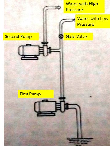
The basic installation of series pumps might be as in Figure 2, but more commonly would be piped as in
Figure 3.

Figure 2.

Figure 3.
When piped as in Figure 3, either pump can be removed from the system for easy service.
When series pumping a system, each pump will pump the entire flow of the system. Each pump supplies the full design flow rate at one-half the required head.
As in parallel pumping, a series pump graph must be developed. This gives a picture of the various pumping conditions.
Putting pumps in series increases the slope of the overall pump curve. Series pump systems lend themselves to be used where high heads are needed.
When a stand-by pumping situation occurs (a single pump running) the flow will decrease. This is exactly the reverse of parallel pumping. The motor horsepower requirements will diminish. There is no danger of burning out a motor (in-line or base-mounted) when in single pump operation on a series pumped system. The greatest load will exist when both pumps are running, so the horsepower requirements of the pump need to be met when both are running.
Another example illustrates series pumping:
System Requirements:
75 GPM at 40 FT HD
Two in-line pumps
Each pump needs to deliver 75 GPM at 20 FT HD
After plotting the system and pump curves, it is found that one pump running will deliver 58 GPM at 24 FT HD, about 77% system capacity for stand-by.
Stand-by capacity has been obtained at no increase in cost!
There is no theoretical limit on the number of pumps that can be run in series.
On larger installations where provisions for future expansion are made, or where a relatively low flow rate for heating and a high flow rate for chilled water-cooling is required, a combination of series and parallel pumping will be employed. A typical installation might be as in Figure 4.

Figure 4.
Figure 4 shows two parallel banks with two pumps in series per bank. Graphs and plots would have to be made for all possible operating points. The four operating points include the following: a single pump, two pumps in series, two pumps in parallel, and two parallel groups of two pumps in series.
If Figure 4 represented a system of about 1700 GPM at 110 FT HD, with correct controls, this type of arrangement would realize big cost savings. Only those pumps needed to maintain adequate velocities need be run. For instance, design conditions might require 50 HP. Most of the time, the system would operate at much less than design conditions, and probably 15 HP would satisfy most requirements.
With parallel, series, and a combination of parallel and series pumping, the system designer has maximum flexibility to design a maximum, cost efficient, pumping system for every centrifugal pumping situation.
For those interested in learning how to develop pump curves, contact: ITT Corporation, Fluid Handling Training and Education Dept., 8200 North Austin Ave, Morton Grove, IL 60053. Ask for bulletin # TEH-1065, and Centrifugal Pump Manual #3100.
dual-pump.pdf (48.1 KB)

All diagrams in the above message is miising any one wants full report of this, please send your mail ID to me I will send you full details.